 AASTHA INTERNATIONAL
The Complete Guide to Industrial Valves: Types, Functions, and Mechanics
A comprehensive, in-depth guide to industrial valves. Learn the core mechanics, components, and distinct applications of gate, globe, ball, butterfly, and check valves.
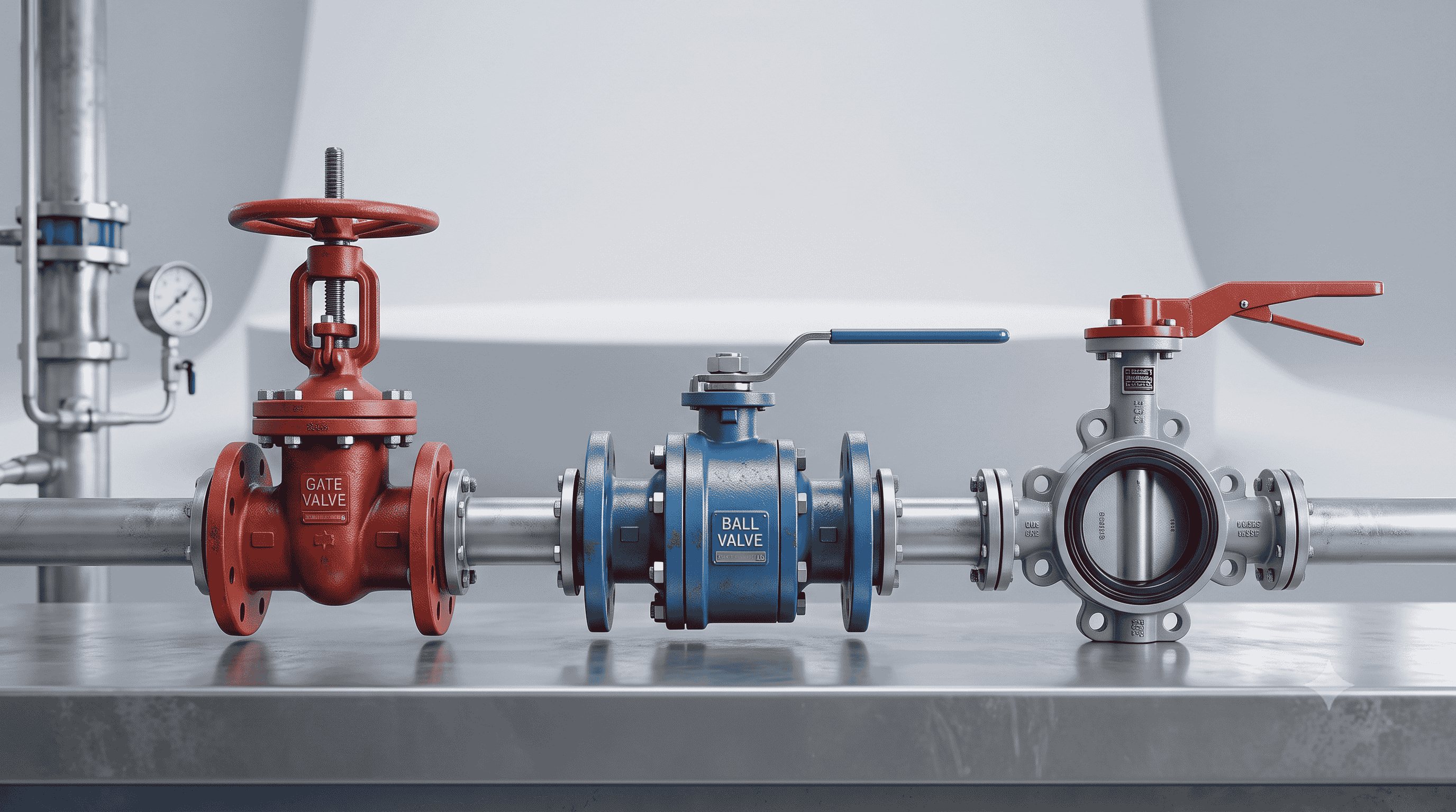
In the vast, interconnected networks of modern manufacturing, chemical processing, and power generation, the control of fluid and gas dynamics is the baseline of operational success. A piping system without effective flow control is merely a vessel; it is the industrial valve that brings that system to life, allowing operators to start, stop, regulate, and direct the movement of media at precise intervals.
Understanding the mechanical nuances of industrial valves is not just an exercise in engineering terminology—it is a critical requirement for maintaining plant safety, optimizing system efficiency, and minimizing catastrophic downtime. Selecting the wrong valve for a high-pressure steam line or a highly abrasive slurry process will invariably lead to rapid mechanical failure, fluid hammer, or environmental leakage.
This comprehensive guide strips away the complexities of industrial piping to provide a detailed, mechanical breakdown of the most common industrial valves, how they function, and where they belong in your process lines.
The Anatomy of an Industrial Valve
Before exploring the different categories of valves, it is essential to understand the shared mechanical components that make fluid control possible. Almost every standard industrial valve shares these core elements:
Body (Shell): The primary pressure boundary of the valve. It houses the internal parts and connects to the piping via threaded, flanged, or welded ends.
Bonnet: The cover for the opening in the valve body. It is often bolted or threaded into place and contains the stem seal (packing) to prevent fluid from leaking up through the actuator mechanism.
Trim: A collective term for the internal, replaceable parts of the valve that come into direct contact with the fluid. This typically includes the disk (or ball/plug), the seat(s), and the stem.
Disk: The movable component that physically obstructs or allows flow.
Seat: The stationary ring or surface within the body that the disk rests against to create a fluid-tight seal.
Stem: The rod that connects the actuator (or handwheel) on the outside of the valve to the disk on the inside, transmitting the motion required to open or close the valve.
Packing: The soft, pliable material (often Teflon or graphite) compressed around the stem within the bonnet to prevent fugitive emissions.
Categorizing Valves by Primary Function
While there are dozens of specialized valve designs, their fundamental purposes generally fall into three distinct operational categories:
Isolation (On/Off Control): These valves are designed to be either completely open (allowing full flow with minimal pressure drop) or completely closed (providing absolute shut-off). They are not meant to be left partially open.
Regulation (Throttling): These valves are engineered to continuously modulate flow, pressure, or temperature. Their internal geometry is designed to handle high-velocity fluid flow without suffering extreme wear or causing severe cavitation.
Non-Return (Backflow Prevention): These mechanical valves operate automatically based on fluid momentum, allowing flow in one direction and slamming shut the moment flow attempts to reverse.
Detailed Breakdown of Industrial Valve Types
1. Gate Valves: The Heavy-Duty Isolators
Gate valves are the absolute standard for on/off isolation applications. They function by lowering a flat or wedge-shaped mechanical barrier (the gate) directly into the path of the flow.
Core Mechanics: When fully opened, the gate retracts completely into the bonnet, leaving an unobstructed bore. This straight-through flow path ensures a minimal pressure drop, which is highly desirable in long-distance pipelines.
Types of Gates:
Solid Wedge: The most common and robust design, suitable for most fluid types but susceptible to thermal binding if the pipe undergoes rapid temperature changes.
Flexible Wedge: Features a cut around the perimeter of the wedge, allowing it to flex slightly to compensate for pipe misalignment or thermal expansion.
Parallel Slide: Uses two parallel spring-loaded discs. They rely on the fluid's pressure to push the downstream disc tightly against the seat, making them excellent for high-temperature steam applications.
Limitations: Gate valves operate slowly, making them unsuitable for emergency shutdown scenarios. Furthermore, if left partially open to throttle flow, the high-velocity fluid will cause the gate to vibrate violently, rapidly eroding the seating surfaces.
2. Globe Valves: The Masters of Throttling
When a process requires precise flow regulation, globe valves are the industry standard. Their internal design deliberately alters the path of the fluid, forcing it through an S-shaped or Z-shaped curve.
Core Mechanics: The valve stem lowers a plug or flat disk directly down into a stationary ring seat. The linear, perpendicular motion of the plug relative to the seat allows operators to finely tune the volume of fluid passing through the valve.
Body Designs:
Z-Body: The standard design with an S-shaped flow path. It offers excellent throttling but introduces a high pressure drop.
Y-Body: The stem and seat are angled at roughly 45 degrees, providing a straighter flow path that reduces pressure drop while maintaining good throttling capability.
Angle Body: The inlet and outlet are at 90 degrees to each other. They function as both a valve and a piping elbow, often used in boiler feedwater systems.
Limitations: Because the fluid must change direction sharply within the body, globe valves introduce significant flow resistance and pressure drop.
3. Ball Valves: Quick-Acting Quarter-Turn Solutions
Ball valves are incredibly versatile and ubiquitous across nearly all industries. They belong to the "quarter-turn" family of valves, meaning a simple 90-degree turn of the handle transitions the valve from fully open to fully closed.
Core Mechanics: The internal sealing mechanism is a hollow, perforated sphere (the ball). When the bore is aligned with the pipeline, fluid flows freely. When the ball is rotated 90 degrees, the solid wall blocks the flow entirely.
Design Variations:
Floating Ball: The ball is suspended between two soft elastomer seats. When the valve is closed, the upstream fluid pressure physically pushes the ball tightly against the downstream seat to create the seal. Ideal for smaller pipes and lower pressures.
Trunnion-Mounted: For high-pressure and large-diameter applications, the fluid pressure is too immense for a floating design. In a trunnion valve, the ball is anchored at the top and bottom. Spring-loaded seats are pushed into the ball to create the seal. This drastically reduces the torque required to operate the valve.
Advantages: Ball valves provide excellent, bubble-tight shutoff, operate in a fraction of a second, and are highly resistant to wear.
4. Butterfly Valves: Space-Saving and Cost-Effective
Butterfly valves are the preferred choice for large-diameter pipelines where installing a massive gate or ball valve would be prohibitively heavy and expensive. They also utilize a quarter-turn mechanism.
Core Mechanics: A central metal disc is mounted on a rotating stem across the bore of the pipe. When open, the disc sits parallel to the flow. When closed, it rotates to sit perpendicular, blocking the flow.
Performance Tiers:
Concentric (Zero Offset): The stem passes directly through the center of the disc. They rely on an interference fit with a thick rubber lining (seat) to seal. Mostly used for low-pressure water and air utility lines.
Double Offset: The stem is offset from the center of the disc and the center of the pipe. This camming action pulls the disc away from the seat the moment it begins to open, reducing friction and extending the life of the valve.
Triple Offset: Features a third offset in the form of a conical seating angle. This allows the disc to close with zero friction, providing metal-to-metal sealing capable of handling extreme temperatures and corrosive chemicals.
Limitations: Because the disc always remains in the flow path, butterfly valves introduce a moderate pressure drop and cannot be used in pipelines that require mechanical cleaning (pigging).
5. Check Valves: Unidirectional Flow Protection
Check valves are unique because they are purely mechanical and self-actuating. They do not require a handwheel, actuator, or external control system. Their sole purpose is to prevent backflow.
Core Mechanics: Check valves rely on the kinetic energy of the forward flow to stay open. The moment flow velocity drops or attempts to reverse, gravity, spring tension, or the fluid itself forces the valve shut.
Key Designs:
Swing Check: A hinged flapper swings completely out of the flow path when fluid moves forward. When flow reverses, the flapper drops back onto the seat.
Lift Check: Similar internally to a globe valve, but the plug is unattached to a stem. Fluid pressure lifts the plug to allow flow; gravity pushes it back down when flow stops. Excellent for high-pressure lines.
Dual Plate Check: Two spring-loaded, semi-circular plates fold inward during forward flow. They are highly compact and close rapidly to prevent the damaging pressure surges known as "water hammer."
6. Specialized Process Valves
While the aforementioned valves handle 90% of industrial tasks, certain processes require highly specialized mechanics:
Plug Valves: Similar to a ball valve, but utilizes a cylindrical or tapered plug with a bored passage. They are highly durable and often used in wastewater or applications containing suspended solids because the sliding action of the plug wipes the seat clean with every rotation.
Diaphragm Valves: Instead of a metal disk, these utilize a flexible elastomer diaphragm that is pushed down into a "weir" to block flow. Because the working fluid is entirely isolated from the valve’s mechanical parts (the stem and bonnet), they are heavily used in ultra-pure pharmaceutical manufacturing, food processing, and highly corrosive chemical applications.
Needle Valves: A miniaturized version of a globe valve using a fine, needle-shaped plunger. They are used for ultra-precise, low-volume flow regulation, typically found in delicate instrumentation, sampling lines, and hydraulic fluid control systems.
Pinch Valves: Features a straight-through elastomer sleeve that is physically "pinched" closed by a mechanical bar. Because there are no internal metal components to wear away, they are the absolute best choice for moving highly abrasive mining slurries or heavy dry powders.
Pressure Relief/Safety Valves (PRV/PSV): The last line of defense in a pressurized system. These valves remain closed under normal operations. If the system pressure exceeds a pre-determined safe limit, the internal spring compresses, opening the valve to vent the excess pressure, preventing catastrophic pipeline rupture or equipment failure.
Critical Parameters for Valve Selection
Selecting the correct industrial valve requires analyzing several intersecting variables. Haphazard selection will result in premature mechanical failure.
Nature of the Media: Is the fluid a gas or a liquid? Is it highly viscous like heavy crude oil, abrasive like a sand slurry, or corrosive like sulfuric acid? For highly corrosive media, standard carbon steel will fail rapidly; materials like duplex stainless steel, Monel, or Hastelloy must be specified. For abrasive media, soft elastomer seats will be torn apart; metal-to-metal seating or pinch valves are required.
System Pressure and Temperature: A valve body must be robust enough to withstand the maximum potential pressure of the system. Valve bodies are standardized by pressure classes (e.g., ANSI Class 150, 300, 600, 1500). Furthermore, high temperatures dictate the sealing materials. Soft PTFE (Teflon) seats are fantastic for tight shut-off but will melt if temperatures exceed 400°F. For high-temperature steam, metal-seated gate or globe valves are mandatory.
Flow Requirements (Cv): Every valve has a Flow Coefficient (Cv), which measures the volume of water (in gallons per minute) that will pass through a fully open valve with a 1 PSI pressure drop. If a valve's Cv is too low, the pump will overwork. If it is too high, the valve will struggle to throttle properly at the lower end of its range.
Actuation Method: How will the valve be operated?
Manual: Handwheels or levers for valves operated infrequently.
Pneumatic: Uses compressed air to open or close the valve. Highly reliable and capable of failing to a safe position (fail-closed or fail-open) upon loss of power.
Electric: Uses electric motors. Excellent for precise, continuous throttling via control room automation (SCADA systems).
By carefully matching the physical properties of the process media and system demands with the distinct mechanical capabilities of gate, globe, ball, butterfly, and check valves, process engineers can ensure reliable, leak-free, and highly efficient piping infrastructure for the lifetime of their facility.